How to Make a Miter Saw Table
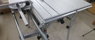
Equip any of the two machines with these ordinary extensions for supporting long workpieces, equipped with movable stops.
Place the platform base on the workbench and place your machine on top, aligning it in the center. Place one of the extensions flush against the platform, as shown in the figure. Determine the distance from the outside of the far post D to the edge of the machine table. You-
cut the two upper shelves E to the same length and width as 152 mm. To use extensions with both machines, determine for each of them the distance from the far rack to the edge of the table and cut the shelves according to the smallest size.
Now, using a saw with a 19 mm wide groove blade, cut a 10 mm deep tongue in the center of each shelf. Press the shelves with clamps to the C/D extensions, drill holes, countersink them and secure the shelves to the racks with self-tapping screws.
Make mobile stops
Determine the width of the movable stop G for the miter saw by measuring the distance from the front edge of one of the extensions to the front side of the stop on the machine table. The width of the movable stop H for a slotting machine is determined by the distance from the front edge of the expansion to the center of the chisel. Determine the distance from the center of the table to the inside of the D pillar, closest to the platform base, to find the length of the movable stops. Having found out the dimensions, cut out the fly from 19 mm material.
Then, using a saw with a grooved disc, select tongues 3 mm deep on both sides of each part at a distance of 60 mm from the front edge and make dust-proof folds with a section of 3 × 3 mm at the top and bottom along each end. Now cut out of hard wood and sharpen two guide rails I with dimensions 11x19x305 mm.
Determine the distance from the protruding end of the top shelf E to the inside of the post D, closest to the platform base, and file the guide rails to that length. Glue them into the tongues of the movable stops, aligning the ends with the shoulders of the dust-proof folds, as shown in the figure. Note. Like a slotting machine with front clamping of workpieces, it may be necessary to make a cutout on the movable stop that allows you to move the stop to the center of the table.
Add extension supports
1. For extension supports D, cut four blanks measuring 152 x 508 mm. To determine their final width, place a miter saw on top panel A. Place a long straight board rule on the saw table and support handle B so that its ends extend beyond the edges of the platform. Measure the distance from the rule to the underside of the bottom panel. Saw the support blanks D to this width and save the scraps.
Read also: LED lamp with battery
2. To mark the centers of the holes on the supports of the extensions D into which the ends of the pipes are inserted ( Fig. 1), mark on one end of the bottom panel A the centers of the openings between the pipe guides C. Draw center lines for the outer opening at the front and for the inner opening at the back.
Align the ends of the support D with the bottom panel A and transfer the center marks of the openings for the pipes.
Rotate the support 90°. Mark on its end the position of the underside of the top panel A.
Now, pressing the edge of the extension support D against the bottom panel, extend the indicated center lines of the openings (photo C). Turn the support over to press it against both panels and the rule, and mark the position of the bottom of the top panel with a line on it (Photo D). This line defines the top edge of the pipe holes so that the top of the supports is flush with the surface of the miter saw table. Using a square, mark the crosshairs by drawing lines from the marks made on the support. Transfer these marks and draw lines on the remaining supports of the extensions.
Align the Forstner drill with the marking lines on support D. Drill 25mm holes in the outer supports and 28mm holes in the inner supports.
3. In the two outer supports of extensions D , use a Forstner drill to mark a hole with a diameter of 25 mm (photo E). Mark these parts as external. Insert a 28mm drill bit into the chuck and adjust the stop so that the cutting edge of the drill bit is aligned with the top line of the holes. Make holes in the two remaining supports. (Larger holes will allow the extension supports to slide easily over the pipes.) Please note: the distance between the centers of the holes should be the same on all supports. When installing supports on pipes on both sides of the platform (Fig. 1), you will need to rotate the ends of one pair of supports.
After drilling mounting holes through the edges of the two outer supports D and through the steel pipes, install the screws.
4. Mill 6mm fillets on the edges of the inner support holes D (Figure 1). Check how the pipes are inserted into the holes of the external supports. Use a round file or sanding attachment for a power drill to widen the holes if you want the ends of the pipes to fit snugly. To maintain the correct position of the supports, do not touch the top edge of the holes with a file or sandpaper. Insert the pipes, align their ends flush with the outside of the external supports, drill mounting holes to secure the pipes and screw in the screws (Fig. 2, photo F ).
5. Cut out the folding stops E and drill 8 mm holes in them (Fig. 1).
6. To attach the flip stops to the outer supports of the extensions D , mark the center on the inside of each stop (Figure 2). Pay attention to the different positions of the holes in the right and left stops - they should be located at the front side of the platform table. After making the counterbores and drilling the holes, insert M6 flange nuts into them.
Read also: How to cook fresh mussels in shells
Level and secure the machines
Using clamps, secure the extensions to the platform base. Reinstall the machine and align it to the center of the width of the base. Pressing a long, even bar against the standard stop of the machine, adjust the position of the machine to align the rear edge of the bar with the rear edges of the upper shelves E.
Make sure the edges of the planks and shelves are parallel. Now remove the strip and extensions. Mark the centers of the mounting holes for attaching the machine, remove the machine and drill holes in the platform base L. Countersink them from below and secure the machine with countersunk screws, adding washers and nuts.
To position the tables of both machines at the same height, cut out two wood spacers, the width of which allows you to make mounting holes for the screws that will secure the machine with the lower table. Sharpen the spacers to a thickness that is equal to the difference in height of the two tables. Now, installing the machine with a low table, make holes. Secure the machine with screws, inserting spacers between it and the base.
Determine the width and depth of the base of your miter saw or slotting machine. If the machine table protrudes beyond the dimensions of the bed, determine the width of the table. Add 38mm to the depth and 178mm to the width to find the width and length of the platform base as indicated in the figure. Then cut out the lower part from 19 mm MDF board, plywood or plastic-coated chipboard to these dimensions.
Determine the height of the machine table and reduce this dimension by 19 mm to find the width of the racks B. Cut out two racks of the same width and length equal to the width of the base A. Press the racks with clamps to the base, drill and countersink guide holes through the base, then fasten the parts with self-tapping screws. To use one pair of extensions for both machines, determine the height of each table. Reduce the larger size by 19 mm and cut out posts of the same width for both platform bases.
READ Stihl 180 Doesn't Develop Power
Assembling the table with your own hands
Tool assembly can be divided into work with several parts. Its main components include a frame, side extensions, side stops, pressure plates and a base platform for the saw.
Let's look at each part in order of importance.
Frame
The frame of the product is best made from a metal profile (aluminum or steel), and its cross-section is usually selected from the existing assortment in the store. The dimensions of the frame, as fundamental for the table, are determined by the free space around, the dimensions of the cutting element and the type of product (non-movable or mobile).
Read also: Laptop bolt won’t come out
In accordance with the dimensions of the saw you are considering, the frame design includes the level of the bottom line of the potential cut and the possibility of changing the position of the saw on the frame.
How to do something yourself, with your own hands. home handyman website
Assembling the table frame
Nail 30x40 mm slats to the bottom of the tabletop around the perimeter to add strength. Saw off the blanks at an angle of 45°, screw the parts with screws of the appropriate length. Don’t forget to lubricate the parts with wood glue before screwing them on. It performs two functions: it glues the surfaces and completely smoothes the cut planes, ensuring the highest stability of the connection.
Wood blocks are reinforced along the perimeter of the tabletop
Assemble the lower table support frame; it may have the same dimensions as the upper one.
Roll the frame from the bars to the size of the tabletop
Attach the legs to it, the height is approximately 1 m, but adjust certain values to suit your own height, in which position it is most convenient to work, this should be the height of the table for the router. Be sure to install corner spacers, otherwise the structure will become loose over time.
The legs are attached to the frame, after which the frame is reinforced with spacers
Check the strength of the structure, try to tilt it, bend it, etc. with great effort. If you find any wobbling, install additional spacers and levers, the number depends on the actual need. You don’t need to pay special attention to the appearance; you are not making beautiful furniture for the living room, but a strong machine for the workshop. The difference in requirements is significant. The frame is ready, install the tabletop in place and you can start working.
What it is
Plywood slabs
The work table for installing a miter saw is a solid base on which this cutting tool, the miter saw, is mounted. This design can be made of metal profiles of various sections and different metals, as well as durable types of plastic. Additional elements (side extensions, guide shelves and stops) can be made from lumber (board, plywood, chipboard or OSB board).
The dimensions of the table depend on the geometric dimensions of the material being cut (lumber, metal profile, tubes or fittings). The design can be permanent or sliding, allowing you to change the surface area of the table, which also depends on the material being processed and the conditions of the work.
The table, depending on the nature of the work being performed, can be made stationary or portable, with legs or provided for installation on a flat horizontal surface located above the floor level.
Manufacturing materials
The correct choice of materials for the production of the table determines its service life and the quality of milling of parts. What materials are recommended to be used for these purposes?
Table. Types of tables according to production material
You can also use glued furniture panels made from natural lamellas; they do not change their dimensions when relative humidity fluctuates, but such a table for a router will be very expensive. It is strictly forbidden to use natural boards due to constant warping in one direction or another, which has a very negative impact on the quality of milling.
A tabletop made of boards is not suitable for the production of a milling machine.
We will give a step-by-step summary of the production of two simple, but very multifunctional tables for a router. The dimensions are given only as general ones; specific ones depend on the type of hand router, and there is an unlimited number of them available. Any model has several parameters that need to be taken into account when performing work.
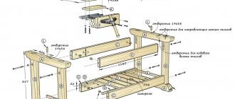
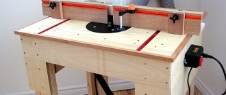
Scheme for assembling a table for a manual router. 1 — side strip for fastening with clamps on trestles; 2 - drawer; 3 — countersunk guide holes; 4 — front wall of the stop; 5 — screw with countersunk head 4.5x42 mm; 6 - scarf; 7 - support base
Making a countertop
Cut a blank for the tabletop from a sheet of plywood. The size can be arbitrary, but more than 80x80 cm. It is awkward to work with very small ones, the workpieces constantly fall, they have to be supported from the back side. Make a mark on the plywood, attach it to the work table with clamps, install a straight edge for the saw and carefully cut off the excess material.
Practical advice. We strongly recommend that all work with an electric jigsaw and portable saw be done only under a ruler. There is no hope that you will get an even cut without this device.
Mark the location of the hole for the cutter. This is also a random setting. Almost everything depends on whether you will subsequently adapt a stubborn ruler for the router, whether a box is provided for collecting and removing sawdust, what parts are meant to be processed, etc. As practice shows, it is recommended to place the hole at a distance of 1/3 of the width from the longitudinal edge.
Marking the hole for the cutter
Make a mark and drill a hole. Its diameter should be only a few mm larger than the diameter of the largest cutter that will be used on this machine. There is no need to make a very large hole for several reasons:
- The larger the gap between the working knives of the cutter and the table top, the higher the possibility that material will get into it. And this provokes the emergence of unsafe situations: the router may jam, or fragments flying off at high speed may injure the craftsman;
- If you have to mill thin parts, then the ends in the cracks vibrate a lot - there is no stop. As a result, it is necessary to cut off uneven parts, which increases the consumption of lumber.
The hole is drilled with a special crown of the appropriate diameter.
Place the router in the hole, making sure it is positioned correctly. Very carefully draw a fishing line around the perimeter of the base. Make sure that the tool does not move during this process; always hold it with one hand.
Try the router on the hole and carefully trace it with a pencil
Set the cutting depth to 5 mm on the router and very carefully cut out the landing site along the drawn contour. Check the hole, stick a router into it. It should fit tightly and not wobble. Adjust the socket to suitable specifications as necessary. Everything is fine - excellent, remove the burrs with sandpaper and continue working on making the table for the router.
READ Stihl 361 Doesn't Rev Up
The landing site must exactly match the contour of the router
Prepare the same mounting nest on another piece of plywood, only now you need to make it through. Cut the part; its dimensions should be approximately 15–20 cm larger than the diameter of the router base.
Make a blank with a cutout of the same shape and size
Place the workpiece on the countertop, align the holes and place them in the router. You need to note the placement and dimensions of 2 parallel guides. A router ruler is installed on them; in our case, it is removed. But you don’t need to touch the guides; they increase the reliability of fixing the router to the table and completely eliminate the possibility of rotating the body. The fact is that over time, the mounting socket may increase slightly in diameter, and the housing with the engine will begin to wobble. The long guides make quite huge levers that hold turning loads perfectly.
The workpieces are combined and the router is inserted
Measure the diameter of the iron pins, set the appropriate depth of the cutter and make grooves for them.
Connect the two table elements and put the router in place. Carefully check the position, manually rotate the rotor, it should not touch anything. Everything is fine - screw the plywood.
After adjusting the parts, screw the workpieces with screws
Fundamentally. Be sure to screw the screws into the previously drilled holes, otherwise cracks may appear. The diameter of the drill for the hole should be several mm smaller than the diameter of the thread of the hardware.
Manufacturing and insertion of the mounting plate
Screw the screws around the perimeter of the stand at a distance of approximately 15 cm, secure the sections between the metal pins separately. Sand the surfaces again. This should not be done to improve the appearance, since the elements are placed under the table and are inconspicuous. By grinding, the surfaces are leveled, small chips are removed, the parts to be joined fit tightly, and the fixation is more reliable. And this is very important for any machine - vibration occurs during operation, weak connections quickly become loose with all the negative consequences.
The entire surface must be carefully sanded
Use small strips of plywood to secure the router in the working position. Turn on the power and check the operation of the tool. It should not wobble; if there are unusual noises, you need to find their cause and definitely remove it.
To fix the router, use two plywood strips
Everything is fine - move on to the next step. Now we need to make a table frame for the tabletop.
Selection of dimensions
It is worth choosing the size of the sawing table depending on the square footage of the workshop. The small area of the room allows you to use a tabletop of 50 x 50 cm. Making the sawing table smaller does not make sense - it will be difficult to use it when processing long workpieces. The universal size, ensuring convenient sawing of laminated chipboards, is 80 x 80 cm.
To comply with safety requirements, it is recommended to place the saw in the middle of the tabletop at a distance of at least 25 cm from the edge - it is this indicator that leads to the minimum width of 500 mm. The location of the saw blade also depends on how it will be used. There are three types of design:
- for longitudinal sawing;
- for cross cutting;
- universal.
The depth and location of the disk installation depend on the workpieces processed on the machine. For boards and plywood, it should protrude above the tabletop by 50-80 mm, for logs - by 110-125 mm. The height of the upper part of the frame made of sheets of plywood or chipboard can be in the range of 35–40 cm. If you make the frame only from timber, this parameter depends on the cross-section. The remaining part of the structure consists of wooden legs, the size of which craftsmen usually choose to suit their height. The overall height of the sawing table is about 1.0–1.1 m, but can be reduced to 900 mm.
Making a combination table
An old kitchen table is used for the machine; these used to be in almost every kitchen. The design, unlike the above, has iron parts; they are installed in more loaded units.
- A sheet of steel 2 mm wide is screwed along the tabletop. This place wears out a lot, the metal significantly increases its service life. The router is screwed to it with screws, the reliability of fixation increases significantly.
A wide iron strip with a cut-out hole for a cutter is placed in the center of the tabletop.
The support rail is secured with metal brackets
The frame is reinforced with iron corners, and an elevator is installed on them to move the cutter
If desired, you can install a dust collection box and additional rulers on the machine to adjust the gap between the cutter depending on its diameter.
What requirements must the table meet?
The professional master spares no expense in purchasing the most modern and reliable equipment - such investments not only pay off, but also bring significant profits. This is his constant work and main income, and the higher the labor productivity, the less unproductive loss of materials and the better the quality, the more profit the master has. There is no point in buying expensive machines and equipment for novice craftsmen; they are completely satisfied with one hand cutter. Accordingly, the machine must be made in such a way that the cutter can be quickly removed at any moment and can be used in normal mode.
The design of the machine must be very simple and immediately reliable
Mobile table for miter saw / Best miter saw stand (built)
The next requirement is that the table must be very simple to manufacture. It can be done with your own hands and using the simple set of tools that non-professionals have.
Due to such requirements, we will not consider options for complex tables; only master carpenters can make them. In addition, most projects require reworking a hand router; after reconstruction, the tool can no longer be used in manual mode; you need to take a second copy. It is economically unprofitable to waste time and money on making a table for a router just to take advantage of a few hours a year, and for ordinary, more frequent work, take another manual router.
READ Do-It-Yourself Kart With Chainsaw Engine
If the need for a manual milling machine is higher, there is no point in building a complex machine
How to make a miter saw table with your own hands?
A tool designed to cut all kinds of materials and surfaces at a certain angle is called a miter saw. It is used in the processing of wood, tiles, plastic, as well as metal and many other construction products.
When working with such a heavy tool, you can make construction tasks much easier if you use a special miter saw table. In production you simply cannot do without this, but at home, for example, in a garage or workshop, you can make such a table with your own hands if you use the drawings. This tool will serve as the basis for placing the saw and will facilitate processing and cutting materials.
Why do you need a router table?
Professional craftsmen do not ask this question; they have separate milling machines. This can be not only woodworking equipment of industrial series, but also special machines for household use. Typically, all-encompassing mechanisms that have a circular saw, a jointer, a router and a drilling machine in different compositions on one frame.
Woodworking machine requires relevant experience
Ordinary hobbyists do not need to take such equipment; an ordinary hand router is enough for them. But situations arise when many people think about creating a table for a router. Why?
- It is not possible to mill by hand, the tool does not move along the straight line of the mowing line, the surface of the parts is wavy. You have to go through one place a couple of times, and this has a negative impact on the final quality.
- The need to mill long workpieces - only on a table can this operation be performed in just one pass.
- There is a need to work on cutters with a complex profile; the manual method does not provide the required surface cleanliness.
Working with a hand router is not always comfortable
You need to see that not all technological operations can be done on a table; there are some that can only be done with a manual milling cutter. For example, it is unrealistic to mill profiles with a closed contour placed in the center of the workpiece on a machine.
Manufacturing process
After all the tools and materials have been purchased, you can proceed to the next steps. make a high-quality circular table with your own hands if you correctly carry out the work according to the drawings and, in fact, the construction of the structure.
The finished table will be level and comfortable for work only if the correct calculations are made. If you are not confident in your own abilities when preparing drawings, you should seek help from a specialist.
DIY miter saw table
Convenient location of the miter saw
A support table, on which you can trim various materials by installing a miter saw, can be purchased at construction tool stores, where a wide range of similar products is available. But sometimes there are cases when it is not possible to buy what exactly is needed for the process of completing the work, then the question arises, how to make it yourself.
Initially, you need to answer several questions on which the parameters of the product being constructed and the material that will be used depend:
- Where will it be installed?
- How will it be secured to the floor or other surface?
- What material and what geometric dimensions are to be processed.
- What type, mounting method and geometric dimensions of the miter saw that will be installed on the table being manufactured.
Making legs
When making a table for a hand-held circular saw, in the next step you can begin making the legs; for this, boards with dimensions equal to 50 x 100 mm are used. The legs must be made taking into account that it is comfortable to work. On average, this parameter reaches 110 cm. The board must be cut along the longitudinal axis, ensuring a small angle on one side.
The workpiece is tried on the work surface so that during installation it stands a little by surprise. The legs are fixed on the outside of the parts to provide rigidity; bolts should be used for this. In order to achieve stability, you can use couplers; they are made from square timber with a side of 50 mm.
Selection of material
To make a circular table with your own hands, you need to remember your carpentry skills, have a lot of patience and a small number of materials and devices.
- plywood 15−20 mm;
- timber 50×50;
- board;
- switch;
- external socket;
- a piece of cable;
- PVA glue;
- varnish;
- screws.
- jigsaw;
- screwdriver;
- drill;
- ruler.
The volume of the countertop will depend on the workshop area. At the same time, it will be uncomfortable to saw huge pieces on a small table. If the part fits completely on the working plane, the cut is made smoother and more accurate. The height of the legs is chosen depending on the height of the master.