A hand router is a unique tool that greatly facilitates the process of making wood products. It is used not only to create technological connections, but also during decorative processing. The main advantage of a manual router is mobility, the ability to work regardless of the availability of a workshop.
DIY table for a router with drawings and production
Why do you need a router table?
To operate the router, it must be securely fixed to the surface of a metal plate attached to a stationary table. After all, it is more convenient to work with a rigidly fixed tool than to hold it in your hands. Purpose of the router: curly processing of edges, selection of grooves. It can be used to process slabs of any type of wood and drill holes of different depths and diameters.
Moving the workpiece along the surface of the tabletop is much more convenient than holding the tool suspended. Fine-tuning the cutters helps to increase the accuracy of the lines drawn on the workpieces.
For reference! Online stores offer a wide selection of milling tables. A particularly wide range of models with complete equipment is presented by the German company Bosch.
You can buy a milling platform or try to make it yourself from fiberboards. A homemade table will cost much less than its industrial counterparts. The following is a look at how you can make a table for a router at home.
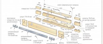
Tabletop drawing
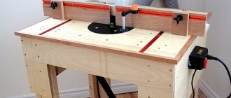
How to make a table (workbench) for a router (wood, metal) with your own hands at home
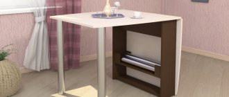
It is possible to produce reliable and practical furniture in one or two days with a minimum of financial investments. The most primitive design is a work area installed on two pedestals.
They begin work by drawing up a drawing and cutting diagrams for the elements of the product.
The drawing shows all the individual elements, places and methods of their fixation, and points of connection of the contraceptive blanks with each other.
What is a milling table: design
The simplest homemade milling table for a manual router should consist of a working surface and a bed. It is complemented by limit strips and adjusting devices.
A do-it-yourself router table with drawings can be found for free on the Internet. Schemes are given in three types:
- small structures that can easily be installed on any work surface;
- side tables with fasteners to another work surface;
- stand alone from other devices, with multiple operating functions and tool storage.
In any of the designs, the base of the table is a strong, smooth tabletop made of hard materials, with fasteners for fixing the router with the possibility of adjustment. Wood and chipboard sheets are suitable for making countertops. The supports can be made of solid timber with dimensions of 40*40 millimeters.
Tabletop small table
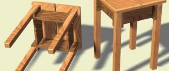
All parts are fastened together using screw conveyors. The device must be stable, rigid in shape, able to dampen vibrations, and at the same time be light in weight, so that it does not make it difficult to change location.
A hole is cut in the surface of the table, onto which a metal plate is placed that can protect the wood from possible damage.
Table design
The simplest design of a milling table involves the presence of three main elements - a working surface or tabletop, a machine base or bed, and additional equipment - a limit bar, adjustment devices, and safety devices.
Among the device layout diagrams that can be found on the Internet, all designs can be divided into three types:
- Multifunctional free-standing devices for working and storing tools.
- Tabletop small-sized tables for milling, which are installed on a workbench or desktop.
- Tables are attachments that are attached to brackets or special seats to a workbench or desktop.
Don't miss: Machine vices for milling machines: requirements according to GOST
And if the former require a certain skill and skill for design and assembly, then desktop structures and milling attachments can be made independently from drawing development to practical implementation.
The basis of the table is the bed - a rigid structure on which the working surface of the milling table - the tabletop - is placed, there is a mount for installing the tool and equipment for fixing and adjusting it.
The entire structure is made of wood and lumber, held together with glue and screws to assemble the furniture. Structurally, a simple table for a router should be of a rigid and stable structure to dampen vibration and at the same time be lightweight so that it can be easily moved from place to place.
Manufacturing of bed and table top
The bed of a homemade milling installation must be highly stable and reliable, since it will bear the main loads. Structurally, it consists of a frame with supports on which the tabletop is fixed. As a material for the manufacture of the frame of the bed, you can use metal profiles connected by welding, chipboard, MDF, wood. It is advisable to first prepare drawings of such a device. They must indicate all structural elements and their dimensions, depending on the dimensions of the parts that are planned to be processed on such milling equipment.
Processing options with different types of cutters
The lower part of the bed from the front side must be deepened by 100–200 mm so that nothing interferes with the feet of the milling machine operator. If you are going to process linings for doors and the ends of facades for them on your homemade machine, then the dimensions of the frame can be as follows: 900x500x1500 (height, depth, width).
One of the significant characteristics of the bed for a homemade milling machine is its height, on which the ease of working on such equipment depends. According to ergonomic requirements, the most suitable height for equipment used while standing is 850–900 mm. It is advisable to make the lower parts of the frame supports adjustable. This will make it possible not only to compensate for uneven floors, but also, if necessary, to change the height of the milling table. To make a turntable with your own hands, just fix special wheels on its legs.
You can make a low-price, highly reliable milling table from the top of an old kitchen table. Such countertops are usually made of chipboard sheets 26 or 36 mm thick, coated with wear-resistant plastic. Their surface ensures good sliding of the workpiece, and the chipboard base perfectly dampens vibrations that occur during operation of the equipment. If you make a desktop for a machine with your own hands, then MDF and chipboard (LDSP) boards with a thickness of 16 mm or more are suitable for these purposes.
Removable tabletop manufacturing technology
| A laminated chipboard sheet is used as a tabletop. Its thickness is 19 mm. The size is 360·540 mm. It corresponds to the size of the resulting window on the machine. Having oriented to the sides, the center is determined. The router shaft must be positioned in the center. Place the support pad in the selected location and outline the pad. |
| A contour is formed on the chipboard sheet. It is necessary to accurately cut the window along this contour. |
| To install the support pad tightly without gaps, you need to drill holes exactly along the edges of the markings. Holes are needed at all extreme points. |
| A jigsaw is used to cut out the window along the drawn contour. If there are irregularities, the walls are refined using abrasive paper and a file. |
| To install the router, you need two steel rods Ø 8 mm. Construction staples are used. You just need to saw them off using an angle grinder cutting disc to a length of 255 mm. |
| The router has holes where you can install rods. To make it easier to install them, any irregularities on the surface of the pins are removed with sandpaper. |
| Having installed the tool exactly above the window, determine the places where the rods will be located during installation. But for them you need to cut special grooves. They are milled. Preparation required for milling. |
| The guide strips are secured using pistol-type clamps. The grooves for the pins will be milled in relation to them. The depth relative to the surface is also set so that on the front of the table the support pad of the router is exactly level with the tabletop. |
| Having completed milling on one side, proceed to a similar operation for the second rod. Guide strips are also installed here and fixed in the desired position. |
| The rods must be pressed from above using clamping bars. Therefore, you will need to prepare a groove where these wooden elements will be installed. First, they are cut out and tried on in place. Then a groove of the required dimensions is marked and milled. |
| Once installed in place, the rods will be securely and tightly pressed in their grooves. |
| It can be seen that the recess under the planks was made to a shallower depth. Structurally, this is how it was originally intended. |
| The router is installed in its place. It is clearly positioned relative to the countertop used. After fixation, it will stand in a given place without the possibility of moving in any direction. |
| Since production is carried out in experimental mode, each stage is checked by preliminary assembly of structural elements. At the moment, we are checking how the wooden planks will press the rods and fix the tool in place. |
| M8 bolts will be used for fixation. They have a secret head. To simplify installation, wing nuts will be used. They are tightened without using a key. At the same time, such a solution allows you to adjust the flatness of the router sole on the front side when tightening. |
| By pressing the parts in place on the reverse side using clamps, holes are drilled. No special markings were made, therefore, to facilitate assembly, the mating fragments are marked with markers of different colors. A countersink is used to countersink holes on the working surface of the table for conical screw heads. |
| On the inside of the clamping strips, holes are drilled to Ø 15 mm. The M8 nuts will be hidden here. Additionally, an auxiliary groove is machined using a round file. It will allow you to press the rods more tightly. |
| The bolts are in place. The nuts are tightened. They will hide in the prepared holes. The assembly and disassembly process will not require much time. The bolts will always be in this position. |
| Now all the elements are easily installed in their places. No additional adjustment is needed. |
| The tabletop can be tried on the table. Therefore, it is first laid with the working surface down. You will need to turn it over to see how it fits on the machine. |
Don't miss: Do-it-yourself lining - manufacturing methods with step-by-step instructions
| The revolution is easy. The tabletop is installed in its place. |
| She stood level with the main table of the table saw. If you recess the cutters, then the additional part will not interfere with the work of cutting parts. Important! The manufactured device did not in any way deteriorate the properties of the main machine on which installation was planned. |
| Cutting out the windows and milling out the auxiliary space inside the tabletop weakened it noticeably. Therefore, reinforcement will be required. To increase the strength of the manufactured attachment, it was decided to use additional bars. They are cut to the required size on a sawing machine. |
| Having cut out the longitudinal and transverse bars, they are screwed to the tabletop. They are pre-lubricated with glue and then fixed with self-tapping screws. All holes are pre-drilled with a Ø 3 mm drill and then countersinked to fit a self-tapping screw Ø 8 mm. Galvanized wood screws are used. |
| Having placed the tabletop on the machine, you can see that the rip fence will not be able to move along its guides. The design of the tabletop itself needs to be improved. |
| The surface to be removed is marked. This type of removal can be done using a router or two passes on a circular saw. |
| Having completed the preparation, the tabletop is put back in place. To make it easier to work at this stage, the router and accessories were removed from it. |
| Once the excess has been removed, the rip fence can be moved around the entire table. It was decided to use it as a clamp for milling. You will only have to slightly modify the auxiliary elements. |
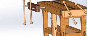
Manufacturing a lift for a milling tabletop
| It is necessary to make several auxiliary elements that will help move the router up and down. The type of elevator being manufactured is shown. |
| By turning it over, you can examine the features of the device. Supports and levers are visible. We need to figure out what and how will work here. |
| The arrow indicates a fixed stand. It bears the main load from the tool. Therefore, there are special requirements for it. It should be strong enough. It will have to counteract the weight of the router, as well as the return springs that are installed on this tool. |
| This arrow points to the axis. The lever can rotate relative to it. The router itself “hangs” on this lever. |
| The design of the lever has a peculiarity. There is a radial convexity here. It rests on the part of the router where there are no ventilation holes. Additionally, it has a thickening in the plastic case, so pressure will not violate the integrity of the instrument’s structure. |
| The bar shown contains a nut. If you rotate the screw, the block will move. A bracket is placed between the lever and the block. Steel loops are installed at its ends. They allow you to adjust the dimensions of all elevator parts. |
| Another important element. It contains the head of the bolt. It rests on a bearing. Therefore, it can be rotated in any direction without much effort. |
| The main support post will be cut from plywood 20 mm thick. |
| To ensure that the stand does not move in any direction during operation, it is reinforced with additional gussets. The result is a product that resembles a rocket. All that remains is to assemble such a device. |
| The “rocket” will be installed on one side of the existing window. |
| To make the bracket, plywood with a thickness of 20 and 10 mm is used. Outer plates made of ten-millimeter plywood are screwed to the lever. The joint planes are first coated with PVA glue. |
| A bearing housing will be installed on the back side of the window. |
| Before assembly, the surfaces of the “rocket” supports are coated with glue. |
| The support legs are screwed with a long self-tapping screw (75 mm). |
| Holes for additional fasteners are drilled on the back of the tabletop. This strengthening is justified; the resistance of the router springs reaches up to 200 N (20 kg). |
| Four more screws are screwed in, the length of which is 60 mm. Attention! When installing self-tapping screws on the front side, the holes must be countersunk. |
| The block is drilled through. A Ø 10 mm drill is used. |
| Here you will need to install a drive nut. To prevent sharp edges from damaging the block itself, drill holes Ø 2.5 mm to a depth of 1.5 mm. |
| The nut is pressed into place. To do this, a block with a nut is placed between the jaws of a vice and squeezed until the nut is finally seated in place. |
| The part gets the desired look. The nut is firmly fixed to the block. The strength is sufficient for the normal operation of this element of the elevator structure. |
| To install the bolt head, you need to drill a hole with a diameter of 20 mm. Here, a socket head will be used in the future, so the hole is prepared with some margin. The drilling depth is 16 mm (19 mm thick chipboard). Important! Plywood 20 mm thick is installed underneath. Therefore, the strength of the structure will not be compromised. |
| After drilling a blind hole, a through hole is drilled. Its diameter is 8.5 mm. This is where the bearing and bolt will be installed. |
| A nut is placed between the bolt head and the bearing. A closed bearing is used, into which chips and dust cannot enter. |
| Turning the tabletop over reveals a long bolt (180 mm). It needs to be fixed so that it can rotate. |
| The washer is installed, and then the nut with the fluoroplastic insert is tightened. The installed fluoroplastic will not allow it to unwind. It does not fit tightly, there is a gap of about 0.5 mm. It will allow the bolt to rotate and transmit forces in any direction. |
| There is a gap between the end of the bolt and the lever that needs to be filled. You need a bracket and overhead hinges. |
| Regular hinges are not enough; additional strips will need to be installed. |
| The length of these strips is selected. |
| Self-tapping screws are screwed into the block. Loops will be put on them. |
| Once put on, the loop will not be able to remove itself from the screw head. The existing groove in the hinges is narrower than the hole, onto which the hardware cap is placed. |
| All that remains is to assemble the entire elevator structure. All structural elements mentioned earlier have been manufactured. |
| By installing the tabletop in the machine window, you can check the functionality of the elevator structure. A screwdriver is used, into which a 13mm socket head is installed. By starting rotations in one direction or another, the cutter moves up or down. Using a measuring tool, you can set the depth of milling grooves on parts. |
Design features of the milling table
An existing workbench can be adapted for a milling machine. But it is more expedient, to eliminate the influence of strong vibration during operation of the cutter, to make a separate structure that ensures the stability of the table.
The main loads during equipment operation are transferred to the base. Therefore, the frame must be reliable and stable. The bed is understood as a fixed base on which the router is located. It takes all the loads and is a structure in the form of a table with a fixed lid. It can be made from a metal pipe, angle, channel, wood, chipboard.
It is necessary to take into account that the router itself is attached to the tabletop from below, which means that there needs to be empty space there.
The router is attached to the table through a high-strength and rigid plate for installation work. It is preferable to make it from metal, textolite or tongue and groove board.
Don't miss: Metal milling cutter: design, types, principle of operation
The base of the router has threaded mounting holes for mounting. If there are no threaded holes, threading is done independently. If the task is impossible, secure the milling device using special clamps.
Start the work by using a milling cutter to select the shape and thickness of the mounting plate. To make it easier, straight corners on the mounting plate must be rounded with a file. A recess in the table top ensures that the plate is positioned flush with the table top.
Make a hole in the center of the plate for the tool to exit, drill holes for attaching the plate to the table. The next step is to drill holes to attach the milling device; keep in mind that the fasteners must be countersunk.
Making a plate for installing a manual router on a table with your own hands
Milling plates are made independently in the following cases:
- creating a milling table with your own hands for a manual or homemade stationary router;
- further unsuitability of the industrial milling table slab.
The material chosen is:
- Sheet steel;
- aluminum plate;
- plexiglass (textolite);
- sheet phenol or carbon plastic;
- MDF;
- laminate;
- thick plywood.
The thickness of the material is selected from 4 mm to 10 mm.
The simplest model of a homemade mounting plate is a two-layer one.
Manufacturing of the supporting part:
- The bottom layer is made of durable material (steel or aluminum).
- The size of the workpiece is selected depending on the specific model of the hand router, but within the range of 200x300 - 250x350 mm.
- Holes are drilled in the corners for screws for fastening to the table.
- A hole is drilled at the intersection of the diagonals of the bottom plate.
- It expands to fit the size of the largest cutter used.
- Subsequently, the central pocket is countersunk to remove burrs.
- The standard getinaks or carbolite overlay is removed from the router.
- Along the edges of the central pocket, holes are marked and drilled for mounting the router into the mounts of the standard lining.
Making the top:
- The top plate is replaceable. Used instead of ring inserts. The material used is less durable, thinner, with a smooth surface.
- All dimensions from the base plate are transferred to the workpiece.
- Holes for fastening to the table and router are drilled with a chamfer for the heads of the mounting screws “sunk”.
- The central pocket is made to fit a specific cutter size.
- Several such plates are made to suit the diameter of the cutting tools used.
The next version of a homemade milling plate is single-layer. It uses replaceable rings to match the diameter of the cutter.
- In the middle part of the base plate, a recess is made with the diameter and thickness of replaceable ring inserts.
- Holes are drilled for fastening the rings.
- They are threaded for screws to secure the inserts.
If necessary, replacement linings are also made independently.
- Round blanks with a diameter 40–50 mm larger than the diameter of the largest cutter are cut out of thin sheet material.
- Holes are cut in the center for a specific cutting tool.
- The holes are countersunk from burrs.
- At the opposite edges of the plates, holes are drilled for fastening the rings to the base plate with a chamfer for countersunk screws.
Various designs
The lightest milling table is considered to be made from a chipboard sheet with a hole for the tool. A wooden guide is mounted to the table, secured with ordinary clamps. Such a design can be easily mounted on a table, installed between stools, and so on.
Craftsmen make milling tables from ordinary 15 mm plywood. The table consists of several parts. You need a lid, a couple of walls, several support bars (usually four), one long block needed to attach the router table directly to the workbench. In the case of an ordinary table, you need to hollow out grooves in the walls in advance in order to install clamps.
There is a special niche in the table top for the cutter. It is made in the shape of a semicircle. This groove can be easily made with a small hacksaw. Holes are drilled into which the mounting screws will go, as well as a movable stop mounted on the table, which is secured with bolts.
Main parts of a milling table
Before starting to manufacture the device for installing the router, a drawing is developed detailing all the elements and fastening points. The basis of the design is a frame that fits tightly to the floor surface. The working surface is attached to it using bolts. A pump is also attached to the base, supplying the cooling mixture to the device, and a container for collecting it.
Schematic drawing of the device
The mechanism can move in vertical and horizontal directions. High-alloy steel is used for the manufacture of guides. For the vertical direction it is attached to the front wall of the frame, for the horizontal direction - to the top.
When processing edges, a stop with parallel bars, a movable carriage, and fine-tuning and locking screws are used to move the cutter in a straight line. The guide rail is similar to a rip fence. Its advantage is that it can be installed at the angle desired by the master.
The tire and stop are attached to the frame using special clamps. The guide bar can be made at home from 2 wooden blocks securely fastened to the workpiece.
Groove Tool
All processing of parts is carried out with milling cutters of different shapes and sizes equipped with a cutting surface. The relationship between the gearbox and the cutting tool occurs using a thermally hardened steel spindle.
Important! The milling device produces a lot of dust during its operation, which poses a threat to the health of the person working on it. To remove dust, an ordinary home vacuum cleaner is adapted to the homemade device.
Without a dust collector, an expensive tool can quickly become unusable.
The dust collector usually becomes clogged with dust within 5-10 minutes. To prevent this from happening, craftsmen came up with a device with a water filter to catch the smallest particles of debris.
Water filter for a vacuum cleaner made from an aluminum pan and a plastic bottle
On the front side of the panel there is an input switch, as well as mode and cooling switches. There are start and stop buttons to turn the spindle on and off.
To increase the working area of the table, you can attach folding wings on supports to it using furniture hinges. Designs with drawers and shelves are very convenient. Dimensions depend on the workshop space.
Convenient, compact design, where everything is at hand
Making the top clamp
When wondering how to make a home-made machine safer to use and ensure ease of processing large workpieces on it, you can equip such equipment with an upper clamp. To create this device, made on the basis of a roller, it is also necessary to prepare drawings.
A ball bearing of a suitable size is often used as a roller for the pressing device. Such a roller is mounted on a holding device that allows it to be fixed at any distance from the tabletop. With the help of this simple universal device, the workpiece of any thickness will be securely fixed when moving along the surface of the work table.
In the video below, a man shows his homemade milling table, which he assembled right on the balcony of his own house.
Types of milling cutters
Milling cutters vary in power, number of motor revolutions, milling depth, processing method, and weight. Lamellar ones are intended only for cutting grooves. Filler holes - paired holes in furniture parts. Rational ones work not only on wood, but also on drywall, plastic, and ceramics.
The best option is trimmers, as they are the most functional. They can create grooves, grooves, and remove chamfers. The most versatile are submersible. They can do all the operations inherent in other types of router.
Electronics at work
It’s quite easy to make a circular and milling table with your own hands, but don’t forget that this tool runs on electric current. Since the start and stop buttons will be located in an inconvenient place for the master, care must be taken to use them. You can make an exit and install buttons to start and stop the mechanism in a convenient place, but this requires knowledge in electronics.
There is an alternative option that is less safe for the router and circular saw. The start button is pressed, and it is in a constantly on state, stopping only by the cable when disconnected from the network.
Preparing for work
You can make a milling table for a manual router yourself. The materials you will need are: wood or rolled metal, wooden beams, angles, self-tapping screws, bolts with washers and nuts. For the countertop, use laminated chipboard or thick sheet plywood. The finished stand for the milling machine resembles a table for a circular saw.
Before you start processing parts, it is worth checking the operation of the device at idle speed, without load.
Some rules:
- The working area should be 2 times the dimensions of the router.
- There should be no fuels and lubricants in the room.
- The device itself must be in good condition.
- Nothing should prevent the spindle from rotating.
- Check the presence of coolant mixture supplied to the milling cutter.
Important! We must not forget to lubricate the friction points of parts in a timely manner.
Table or machine?
However, hand routers are not cheap tools. There seems to be no fundamental difference in the design of it and the milling head of a vertical milling machine. A motor suitable in power and speed for a homemade milling machine may be waiting in the closet for some use. So what is better to do for milling work on wood: the entire machine from scrap materials, or buy a manual router and a table for it?
Homemade wood milling table
Note: Factory-made tables for hand routers are sold in the same way as drill stands that convert them into drilling or lathe machines.
It's about vibrations. The vibration of a machine with a workpiece is the worst enemy of cutting materials. In milling operations, the influence of vibration on the quality of processing is especially strong. If a drill or cutter (except for a chisel in a slotting machine) bites into the workpiece once and then moves through the material more or less smoothly, then the cutter hits the workpiece at least twice on each revolution. Shaped cutters with cutting edges curved in 3 planes reduce this drawback, but do not eliminate it completely - a cutter that does not hit the workpiece will not cut anything from it.
A homemade milling machine with a motor made from junk generally shakes as best it can. Vibration dampening measures available in the home workshop provide a quality of work more suitable for simple carpentry work. In manual wood milling machines, vibration damping is already provided structurally. Installing the router into the table further reduces the “shaking”, and the entire unit becomes suitable for fairly delicate carpentry work, incl. over the front parts of furniture, decorative parts and other important parts. So there is still a fundamental difference between a homemade milling machine and a table for an existing manual milling machine.
Manufacturing stages
Before assembling the structure, you should prepare all its components and check their compliance with the dimensions indicated in the drawing. Step-by-step manufacturing instructions:
- making a frame, coating wooden parts with paint and varnish, priming metal parts before painting;
- securing the working surface to the bed;
- making a recess in the frame for installing a metal plate with a slot for a cutter, onto which the tool itself will be attached from below;
- insertion of guides for mounting the stop.
Note! All connections must have a countersunk head and not rise above the work surface.
For safety reasons, the on and off buttons are installed on the side surface of the frame.
Marking the tabletop for the profile, mounting plate, grooves
What are they needed for?
To securely fix the router, there is a plate for installing it in the table. When attaching the device directly to the table, the overhang of the cutter to the thickness of the table top is lost. Therefore, a hand router is attached to a plate about 4 mm thick. The plate is fixed on the table. Its dimensions are chosen optimal to prevent deflections.
The mounting plate is a rectangular plate with a round hole in the middle. At the corners there are pins “sunk” for fastening to the table. Near the central pocket there are holes for the pins for attaching the milling device and replacement rings.
How to make a mounting plate
Along with metal, plexiglass and textolite are suitable for working plates. It is worth remembering that the size of the cutter overhang depends on the thickness of the plate.
Please pay attention! Materials such as hardboard or getinax are not suitable for making a mounting plate. They do not tolerate vibration and high temperatures emanating from the motor.
Approximate marking of the mounting plate
When assembling the structure, fasteners and bolts with special heads inserted into the frame openings play an important role. Without them, rigid fastening of the workpiece to the working surface is impossible. The number of motor revolutions and the rotation speed of the cutter depend on the drive.
Drive for a homemade milling machine
In order for the homemade wood router you made to be highly productive and functional, you need to equip it with an electric drive of sufficient power. If you plan to use your machine to process wood parts with shallow recesses, a 500 W electric motor will be sufficient for it. However, equipment with a low-power drive will often shut down, which will negate any savings from purchasing a weak electric motor.
The optimal choice for such machines are electric motors, the power of which starts from 1100 W. Such an electric motor with a power varying between 1–2 kW will allow you to use your homemade device as a real milling machine for processing wood products. In addition, you can use any type of cutter on this machine. To equip the machine drive, you can use electric motors that are installed on stationary equipment (for example, drilling machines), as well as on hand tools (drills, grinders, hand routers).
More serious factory equipment costs significantly more. For example, the price of such a Kreg table starts at 22 thousand rubles
You should pay attention not only to the power, but also to the speed of the electric motor. The higher this indicator, the better quality the cut will be. Electric motors, as you know, can be powered from an electrical network with a voltage of 220 and 380 V. There will be no problems connecting the former, but three-phase asynchronous motors will have to be powered using a special star-delta circuit. Connecting according to this scheme will make it possible to use the electric motor at its maximum power and provide it with a smooth start. And if you directly connect such an electric motor to a 220 V network, you will lose 30–50% of its power.
Safety at work
Working with a router without following safety precautions is associated with the risk of injury. The first thing you need to do before turning on the machine is to read the instructions for use. It doesn’t hurt to check the serviceability of the electrical part of the machine and cutting tools.
There should be no defects on the cutters. They must be securely fastened with a vice or other clamp. The cutter is replaced only when the plug is disconnected from the socket. Do not forget that even when the electrical power is turned off, the cutter continues to move by inertia for some time. There is no need to rush, it is better to wait until it stops completely.
When working with the machine, you must use goggles or a special shield to protect your eyes, and your respiratory system - a respirator or dust mask. Hearing is protected from excessive noise with headphones.
Important! You should not work as a milling cutter in a house or apartment, exposing your loved ones’ breathing to dust and their hearing to loud sounds.
Making a homemade tool will delight you with its low price, ease of operation, ease of assembly and maintenance.
Assembly Rules
Assembling a milling table with your own hands should be done in stages. First you need to decide on the tabletop and make a hole in it for the tool. Next, material supply control systems are attached.
In this case, it is necessary to accurately determine the places of their attachment down to the smallest detail, since the quality of further work depends on this.
The milling machine itself must be firmly secured under the tabletop. It should not dangle or hang; any movements can lead to injury during operation or equipment breakdown. It is better to fix it with self-tapping screws, for your own peace of mind.
Next, install the bed. It is very firmly attached to the tabletop to withstand all loads and vibrations. You can make a milling table with legs, but you should take care of their thickness and fastenings.
The main thing in this method of work is to make the most convenient workplace for the master. And in this regard, the master himself works with all dimensions, knowing what he actually wants to get as a result.